
The first order slope of a woofer
Here you can see an example of how to get a first-order slope from a real-world woofer:

From the bottom end to around 50Hz. there is a rising character and it’s 6dB. This is due to the limited acoustic load of the typical cabinet for an 8″ driver. From 500Hz up to 900Hz you can see a 2dB plateau and this is done by the corners of the cabinet. Up to 5kHz, the driver is flat and at 5kHz there is a small peak. Really not bad for an 8″ driver, but how does it look if you need to “tailor ” it to a first-order slope?
Well, look at this:

It can be done! This was calculated for a crossover frequency at 1500Hz – so over more than one octave, the response curve is still falling with 6dB.
Here is a schematic of the passive filter to get the above behaviour:
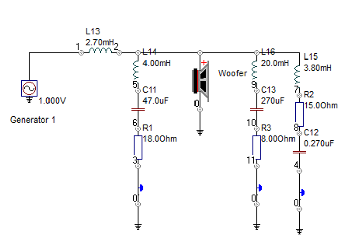
The main inductor is 2.7mH….OK; that’s easy. The LCR with 4mH, 47uF and 18 Ohm for the 500-900Hz uplift, the 20mH, 270uF and 8 Ohm compensates an impedance peak at low frequencies that react with the 2.7mH and makes the 100Hz area boomy. The last LCR is for the 5kHz peak. This is not 100% optimised but shows what is necessary to create a real 6dB slope.
The woofer is the easy part, the tweeter is more complicated, as it has to run flat from 500Hz up….nothing a standard dome can do.
Watch this space for more