in the last article, I explained how to adjust the distance of drivers for best integration. But what happens if a real-world driver comes into place. Every driver has a bandpass behavior. It falls down at low frequencies with 12dB and at higher frequencies with 12dB or even more. But let’s assume, it’s 12dB.
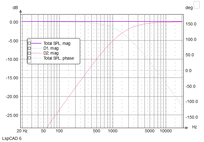
Here again the ideal situation of a pure 6dB filter:
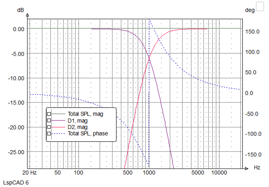
The tweeter in our sample box uses a BMR driver. It sits in its own enclosure and has a resonance frequency of 200Hz with a Q of around 0.8. So it drops off with 12dB per octave below 200Hz. Adding this to our simulation looks like this:
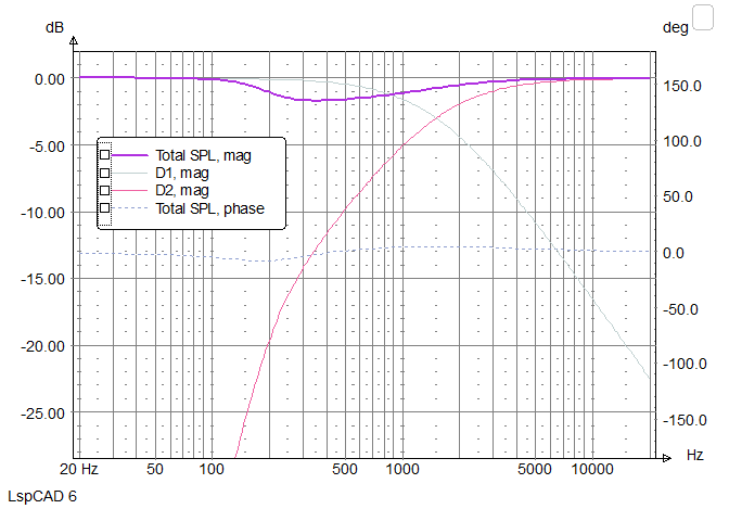
Unfortunately, this additional filter far below the crossover frequency ruins the response curve already. But also the woofer rolls off at 5kHz and so a second-order filter at 5kHz gets added to the woofer.
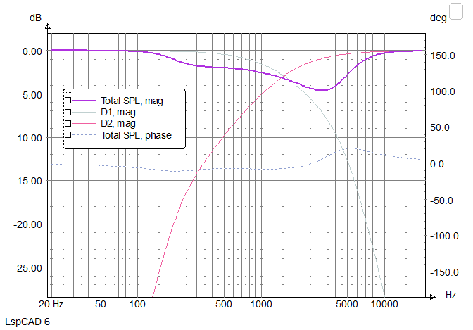
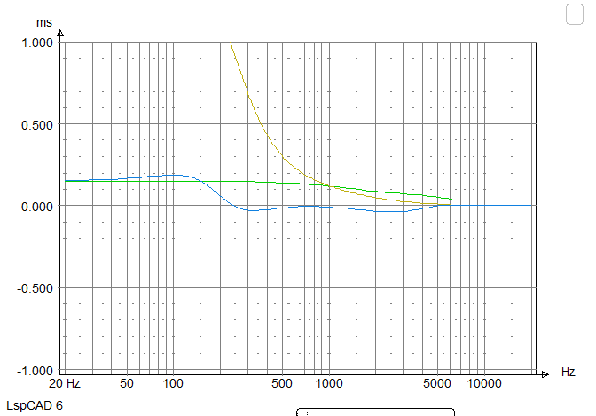
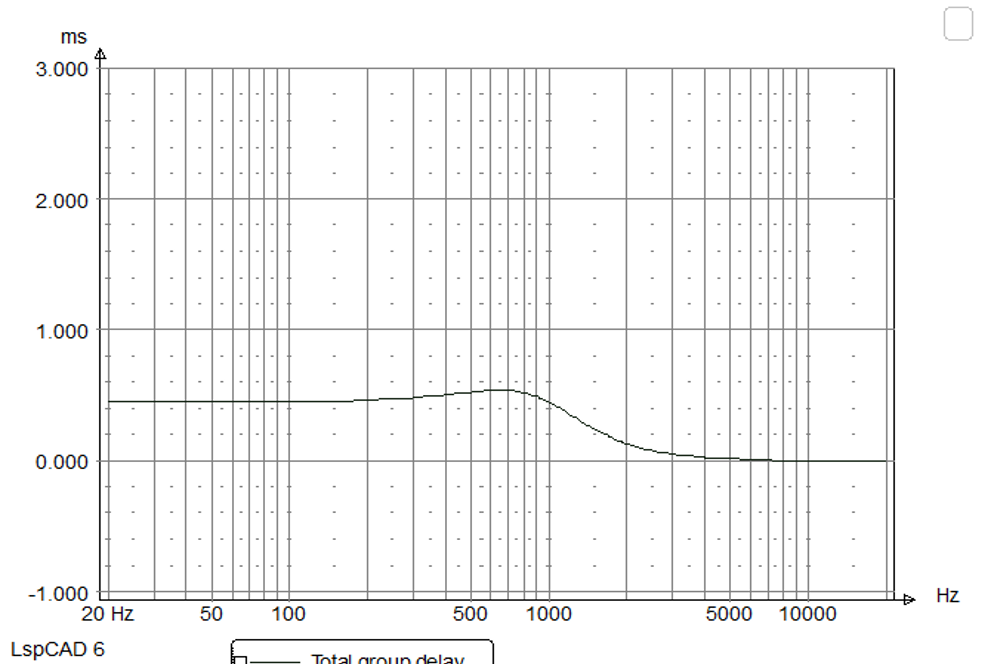
That disturbs the response curve even more – and this speaker is on the theoretical perfect “position” . How about the group-dealy? It this still as good as before?
Unfortunately, it is not. However, the curve is not so bad and the delay max. 0.15mS.
Conclusion:
The theoretical advantages of a first-order crossover are not really working without drivers that got extremely wide bandwidth. Wore work to be done!
As described in the article before, the drivers need to be placed at the correct distance to the listener.
Placing it on a standard stand would give a few centimeter delay for the woofer. Not acceptable for our first order project, so the tweeter needs to go back in relation to the woofer.
The easiest way is to tilt the cabinet. A quick calculation gave around 11° with the 8″ woofer and a 46mm BMR driver
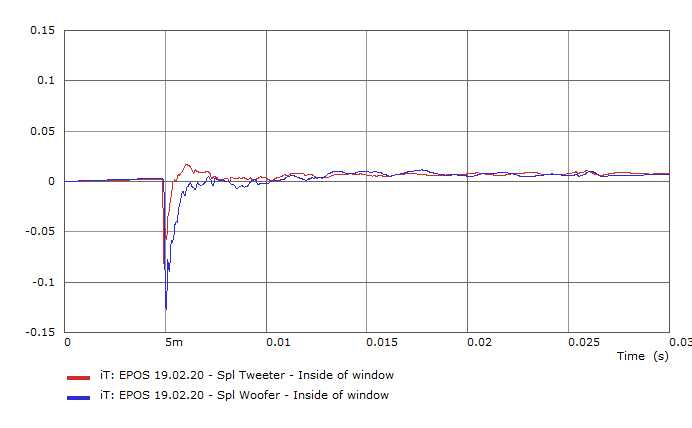
It’s easy to measure if that fits in reality. The box was standing in our anechoic chamber and a KLIPPEL TRF was performing the task. Microphone distance is around 2m. Please note, Klippel places the impulse upside down.
Yes, it does. Both drivers are starting at the same time….maybe a few millimeters still needed to be perfect, but so far, I can see the way to adjust the timing between the drivers.
First of all, it is important to realize that every crossover filter is a compromise. There is no free lunch and therefore it is important to know about the compromises.
One of the most popular crossover topologies is the 4th order LKR filter. Properly designed, it adds together two drivers nicely, as there is no phase shift. This allows very nice imaging with only little overlap between the drivers.
At the crossover point, both drivers are down 6dB……that also means that the overall radiated power in the crossover region is somewhat reduced (3dB). Above and below the listening position, the level drops. That is not necessarily bad, as nobody is keen on reflections from the ceiling or the floor of a room. In case of a 2-way system, it also helps with the hard break in directivity.: the woofer normally beams already, but the tweeter radiated wide. With carefully chosen filtering, you can get great results.
4th order LKR filter
There is another negative “feature” of any higher-order filter is the group delay. This describes how much time the signal needs to travel through the filters. One could think, this is time is constant over frequency, but it’s not. The graph below shows the group delay of the filter shown above.
It can bee is seen that the lower frequency part takes around 0.4ms longer than the tweeter part. At the crossover frequency, there is an extra small delay. Again, this happens with all filters and the delay changes with filter order and type of filter. And this is true for all filters – electrical or acoustic filters. This behaviour has nothing to do with the possible mechanical offset of woofer and tweeter,
Now back to the first-order filter. This filter shows only a very limited filter functionality with big overlapping.
In this filter, the level is down 3dB at the crossover point and properly done, should give a very even power response. Both drivers are in phase,.
Looking at the group delay, it can be seen that both drivers combined don’t show any group delay!
So does a 6dB also have some negative points? Yes, as said before, there is no free lunch. The first problem is covered in an earlier article, showing how to make a 6dB slope for a real-world drive unit. No easy task.
The next big problem is the position of the drivers in relation to each other. Only a perfect mechanical time alignment gives a good result. Moving the driver position only 5cm (mechanical offset of a driver or different height at the listening position) kills the whole idea of the 6dB topology.
Below the behaviour of our 4th order LKR filter with 5cm offset between the drivers and the same for the first-order filter
The next simulation shows the combination of two drivers, but now the other driver is delayed. Here the 4th order crossover:
As can be seen, the result is very similar, meaning that the effects are symmetric. Now the same with 6dB crossover:
This time, we are getting a suck-out at the crossover frequency and the result looks wired. Maybe this makes you understand why some speaker measurements are looking so wired without sounding completely broken.
Conclusion
The 6dB crossover has some nice benefits, but they are not easy to realise in a product. Nowadays, simple crossovers with only one component per driver are called 6dB, but this is not really true, as only the combination of acoustic behaviour and electrical filter gives you the benefit of first order. The only company, who really used the true 1st order crossover is no longer in business. Time to do it again.
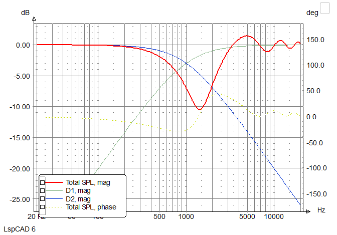
Here you can see an example of how to get a first-order slope from a real-world woofer:
From the bottom end to around 50Hz. there is a rising character and it’s 6dB. This is due to the limited acoustic load of the typical cabinet for an 8″ driver. From 500Hz up to 900Hz you can see a 2dB plateau and this is done by the corners of the cabinet. Up to 5kHz, the driver is flat and at 5kHz there is a small peak. Really not bad for an 8″ driver, but how does it look if you need to “tailor ” it to a first-order slope?
Well, look at this:
It can be done! This was calculated for a crossover frequency at 1500Hz – so over more than one octave, the response curve is still falling with 6dB.
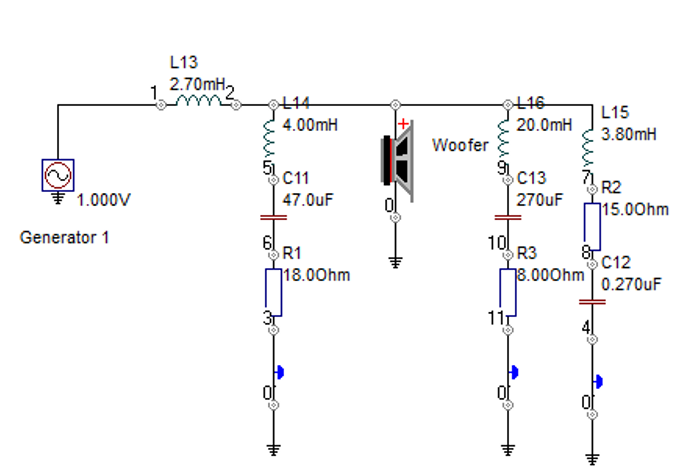
Here is a schematic of the passive filter to get the above behaviour:
The main inductor is 2.7mH….OK; that’s easy. The LCR with 4mH, 47uF and 18 Ohm for the 500-900Hz uplift, the 20mH, 270uF and 8 Ohm compensates an impedance peak at low frequencies that react with the 2.7mH and makes the 100Hz area boomy. The last LCR is for the 5kHz peak. This is not 100% optimised but shows what is necessary to create a real 6dB slope.
The woofer is the easy part, the tweeter is more complicated, as it has to run flat from 500Hz up….nothing a standard dome can do.
End of last year, I bought the EPOS brand and now I’ll start developing new EPOS speakers. I studied all the papers I could find and I was reading all the interviews I could find made with Robin Marshall, the original founder of EPOS.
The first information I found, did not really fit what I thought he did and so I was wondering why somebody wrote about high hysteresis rubber surrounds, as I try to avoid them to keep the dynamic as high as possible.
In the end, I wound an interview that made a lot more things more clear to me…..click the link below to read about Robins opinions.
Start Quote: “Simple crossovers place huge demands on the drive units and in almost every respect are more difficult to engineer properly than complex ones. In a perfect world I would use first order electro-mechanical slopes because nothing else can equal their time and frequency domain performance. Lots of things need to be right to make them work and it certainly isn’t a trivial engineering exercise. It’s the fastest route I know to exposing all the deficiencies you built into your drive units!
First order electrical slopes designed in isolation of the responses inherent to the drive units are not the same thing as first order electro-mechanical slopes, as I sure you know, and may or may not provide the same performance benefits”. End Quote
Here you can read the first important thing about the new EPOS. We will not make a crossover with as little parts count as possible, but we will do a fist order slope for woofer and tweeter.